Plant Moisture Sensor
Plant Moisture sensor
A simple, smart and durable circuit that tells you exactly when to water, without damaging the electrodes or guessing the real condition of the soil.
Why this design matters
- It truly monitors soil moisture instead of acting like a rough indicator with limited accuracy.
- The alternating current applied to the electrodes reduces electrolysis and greatly limits corrosion.
- The detection threshold can be adjusted to match the plant type and the soil characteristics.
Table of contents
Why install a plant moisture sensor?
Many indoor plants suffer less from lack of light than from irregular watering. A reliable moisture sensor removes the guesswork and helps you water at the right time, not too early and not too late.
The value of this project goes beyond a simple LED warning. The circuit is built to provide stable, usable information that remains practical for day-to-day monitoring across different plant types.
The sensor
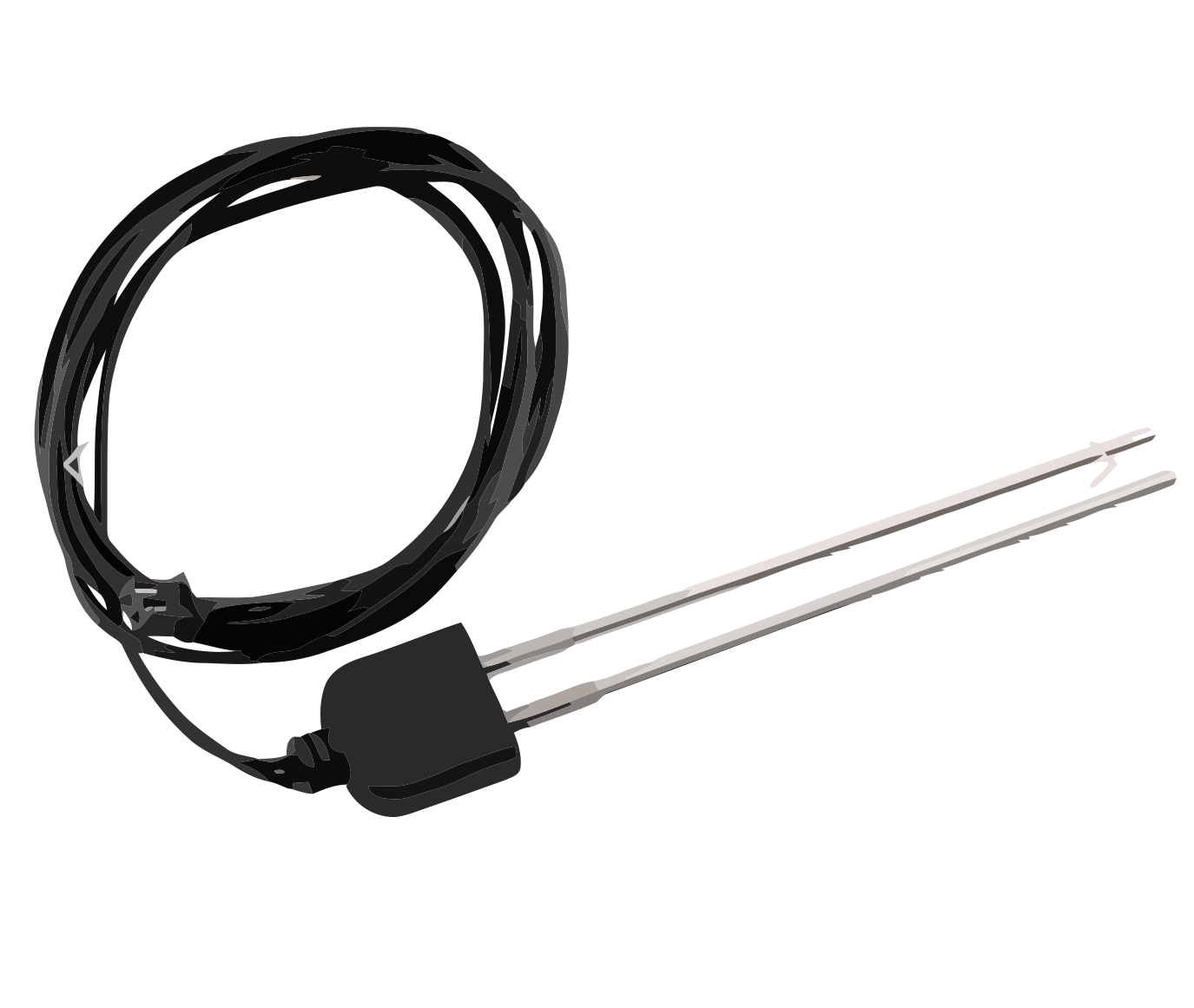
Soil humidity sensor which could be used for this project
If you're interested in this project...
Are you looking for peace of mind when it comes to watering your plants? Contact Luxjim using this form:
Contact form. To discuss a quote or get professional advice if you’d like to carry out the project as DIY.
How the circuit measures soil moisture
The system is based on two electrodes inserted into the potting soil. As soil moisture changes, the electrical resistance between those two points changes as well.
A 4047-based oscillator generates two complementary signals that inject an alternating current of about 58 Hz into the electrodes. This design choice is important because it prevents the electrolysis issues commonly found in low-cost DC soil sensors.
The voltage measured at the P1 potentiometer is then compared to a stable reference of about 2.5 V. As soon as the soil becomes too dry, the red LED turns on to indicate that watering is needed.
How to read the LEDs
Green LED: the soil still contains enough moisture.
Red LED: the measured resistance indicates dry soil.
Between those two states, the inherent capacitance of the soil can create an intermediate zone where both LEDs appear to participate in the indication. That is actually useful, because it shows the plant is getting close to the critical threshold.
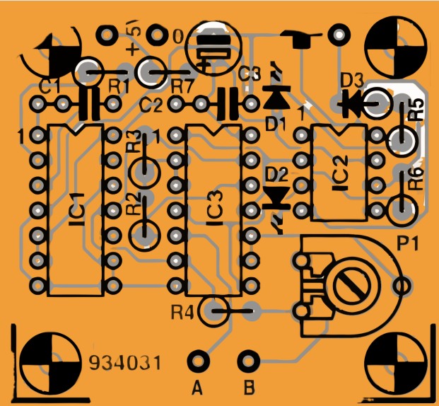
Key electronic components
Sensor stage
- IC1: 4047, used as the oscillator.
- IC2: TLC271, comparator / operational amplifier.
- IC3: 4066, analog switch.
- D1: low-current green LED.
- D2: low-current red LED.
- 1N4148, used as the signal diode.
Passive parts and adjustment
- R1: 100 kΩ.
- R2, R3: 15 kΩ.
- R4: 820 Ω.
- R5, R6: 680 Ω.
- R7: 22 Ω.
- P1: 1 kΩ trimmer to set the threshold.
- C1: 39 nF, C2: 100 nF, C3: 10 µF.
Workshop tip: graphite is an excellent material for the electrodes. It is inexpensive, stable, and much less vulnerable to corrosion than ordinary metal probes.
Simplified sensor diagram
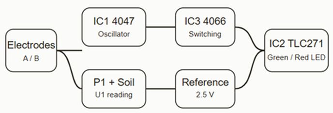
The 4047 generates the alternating signal, the 4066 conditions the measurement path, and the TLC271 compares the soil-dependent voltage with a stable reference.
Simplified 5 V power supply diagram
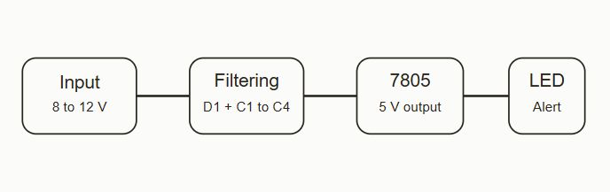
A regulated power stage built around a 7805 can feed one or several sensor modules, with a current draw of about 5 mA per unit.
Setup, electrodes and practical tips
In practical electronics, the difference between a gimmick and a useful circuit usually comes down to details: electrode quality, stable power supply, and proper threshold calibration. In this project, those details are exactly what make the sensor worthwhile.